EML2322L / EML4502
Manufacturing Resources
This
webpage outlines various cutting tools available in lab and tips for their
selection and use. This
condensed sheet lists each tool size stocked in the lab for quick
reference. You are not limited to
these tools; however tools not on this list must be purchased prior to
manufacturing, as must tools for working with ferrous materials other than low
carbon steels (e.g. AISI 1018, or other 1XXX series low carbon steels).
Each section includes links to common vendors to purchase tools not stocked in
lab.
Table of Contents
Reamers & Precision Hole Making
Taps, Dies & Threading
Damaged / Stripped Fastener
Removal
Thread Repair
Drills & Rapid
Hole Making [RETURN TO T.O.C.]
Basics
of … Drills (Good Technical Info)
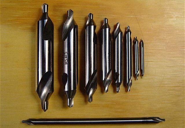
HSS
Imperial Center Drills (sizes and lengths shown in table below)
|
CENTER DRILL BIT
SIZES |
|||
|
Center Drill No. |
Body Dia. |
Drill Bit Dia. |
Drill Bit Length |
|
0 |
0.094 |
0.031 |
0.038 |
|
1 |
0.125 |
0.047 |
0.047 |
|
2 |
0.188 |
0.078 |
0.078 |
|
3 |
0.250 |
0.109 |
0.109 |
|
4 |
0.313 |
0.125 |
0.125 |
|
4½ |
0.375 |
0.141 |
0.406 |
|
5 |
0.438 |
0.188 |
0.188 |
|
6 |
0.500 |
0.219 |
0.219 |
HSS
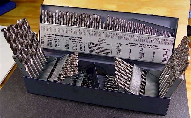
Jobber Drill Set Containing Fractional (1/64” – ½” by 1/64’s), Numbered
(#1-#60), and Lettered (A-Z) Drill Sizes
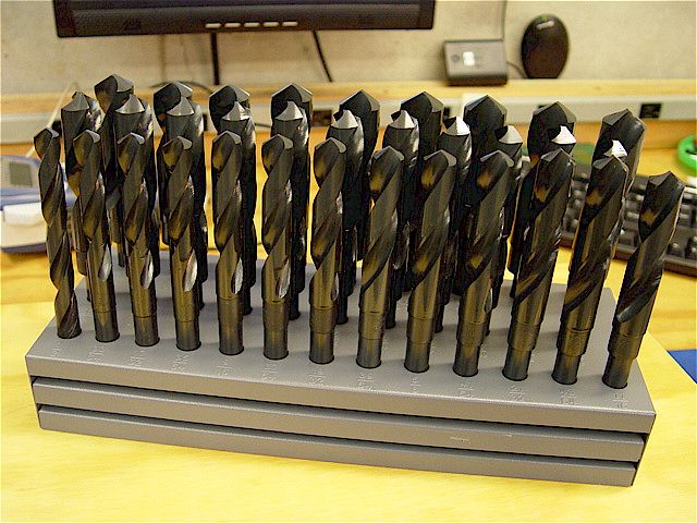
Silver
and Deming HSS Imperial Fractional Drills (9/16” – 1” by 1/64” increments, and
1-1/8” – 1-1/2” by 1/16” increments)
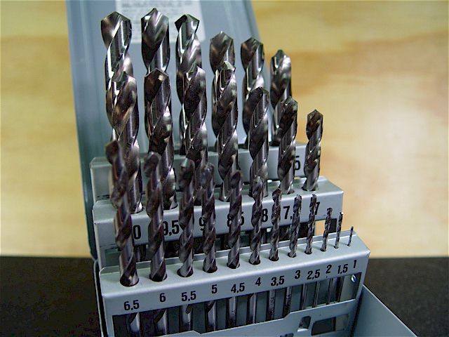
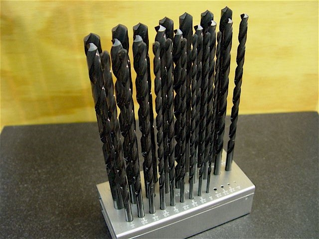
Metric HSS
Jobber Drills (1 – 6mm in 0.1mm increments, 6 – 13mm in 0.5mm increments)
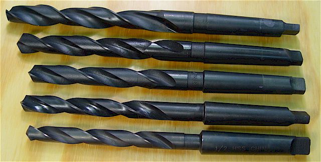
Taper
Length (i.e. Long) HSS Drills (9/16” – 1” in 1/16” increments, 1-1/8” – 2” in
1/8” increments)
Extra-Long
HSS Imperial Fractional Drills (1/8” – 1/2” in 1/64” increments)
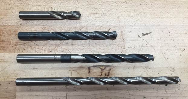
Comparison
of common drills from top to bottom: stub / screw machine length, jobber
length, tapered length, extra-long (aircraft) length
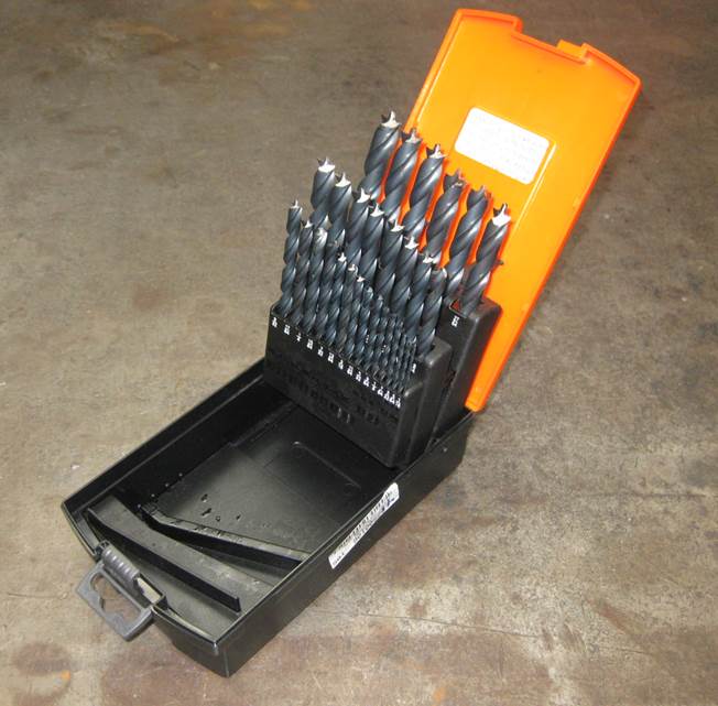
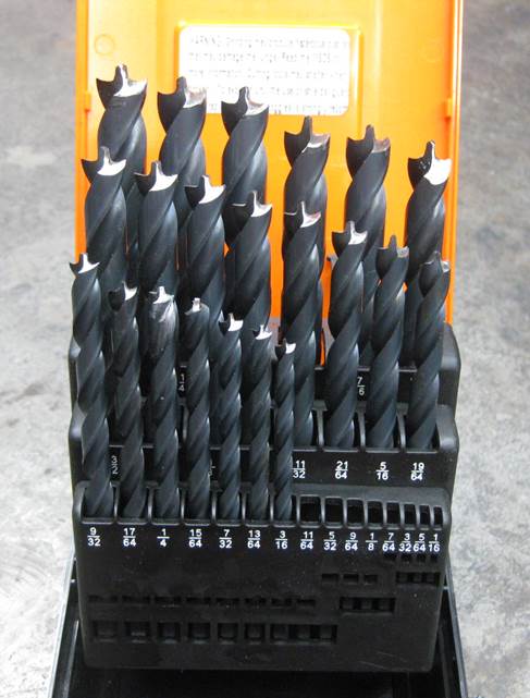
HSS Flat
Bottom Drills (1/64”-1” by 1/64 increments, and 1 1/8” – 1-1/2” by 1/16”
increments)
Process
Tip:
Always use a regular tapered drill to create the hole and only use a flat
bottom drill to finish it. In other words,
NEVER try to drill the entire hole with a flat bottomed drill, as doing so is
tremendously dangerous!
HSS
Sheetmetal Drills (3/16”-1/2” by 1/64 increments
Process
Tip:
Always use these drills in drill press or milling machine, as they are very
aggressive and can cause injury if used in a hand drill!
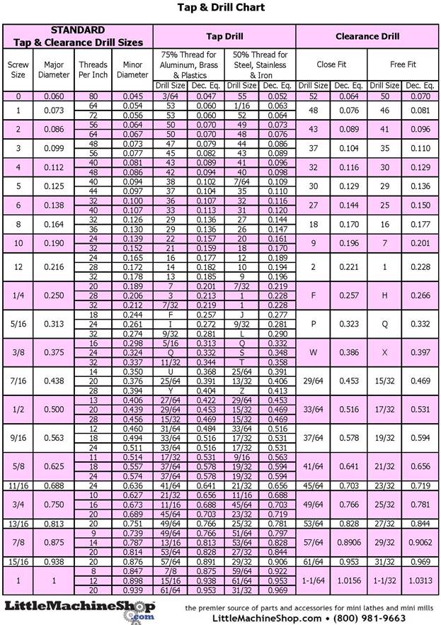
Imperial
Tap and Drill Chart (Click for PDF Version)
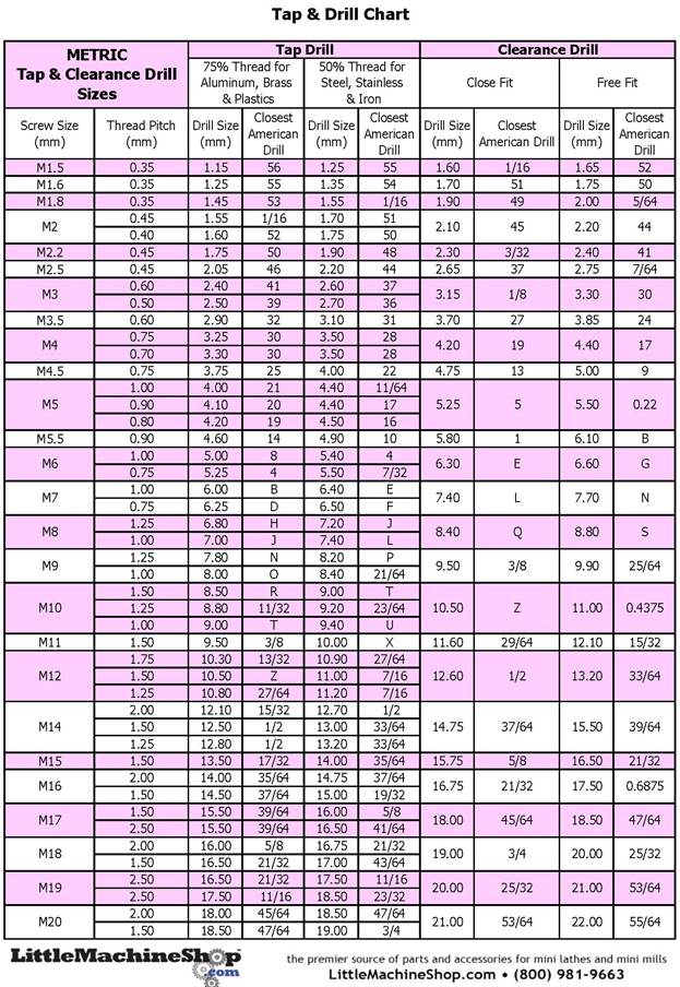
Imperial
Tap and Drill Chart (Click for PDF Version)

Drill
Sizes Chart (Fractional, Lettered, Numbered, & Metric) (Click for PDF
Version)
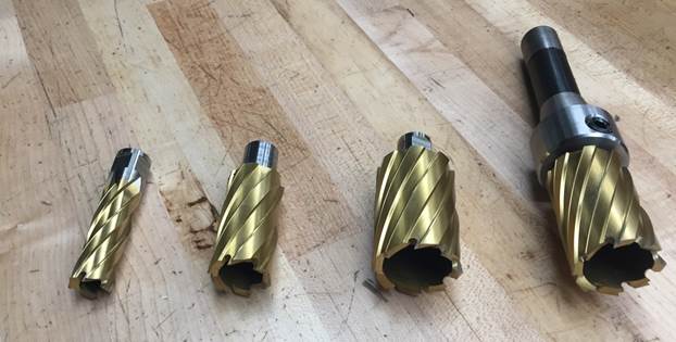
Annular
Hole Cutters (sizes 5/8” – 1-1/2” in 1/8” increments) and R8 Milling Machine
Arbor.
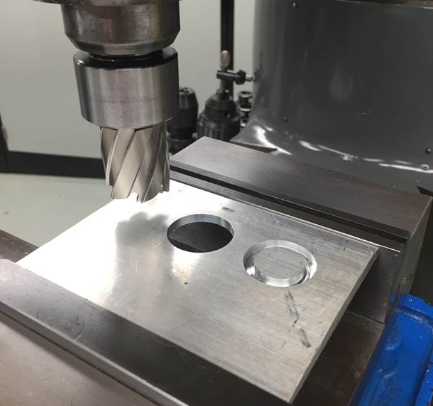
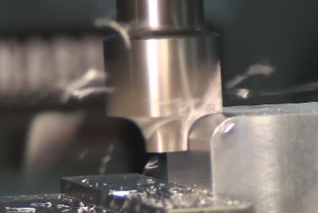
Annular
Hole Cutter In Use on Milling Machine (note the
annular groove it cuts through the workpiece, giving the cutter its name)
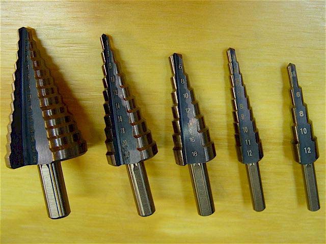
Stepped
Drill Bits for Creating Clearance Holes Thru Thin Materials (1/8” – 1-1/4” in
1/16” increments)
Reamers &
Precision Hole Making [RETURN TO T.O.C.]
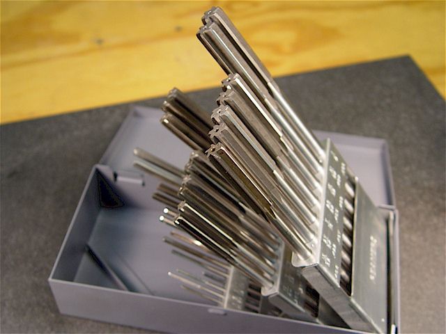
HSS Reamers: Fractional (sizes 1/16” – ¼” in 1/32”
increments), Lettered (A – Z), and Numbered (#1 – #60)
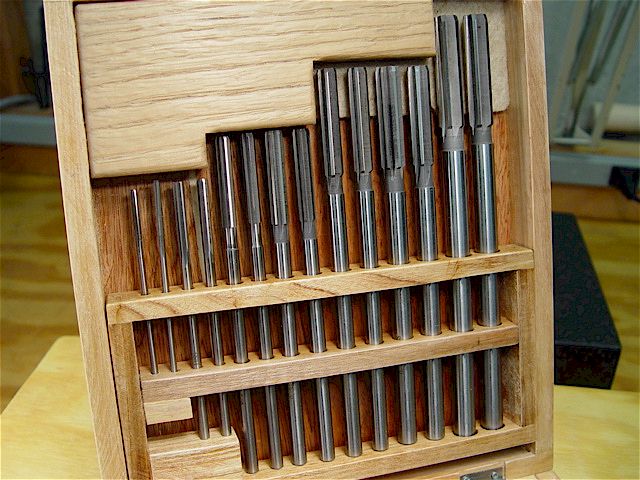
HSS Reamers: Fractional Over and Under Sized (±
0.001” of the standard fractional sizes: 1/8” – 1/2” in 1/16” increments)
Reaming
Tips Reference Document
Process
Tip #1: When using reamers, leave 3% allowance for the reamer to remove. For example, if reaming a
Ø ¼” bore, drill the hole to 0.250” – 3% ≈ Ø0.243” in preparation for
reaming. The 1/64″ rule we use in
lab works pretty well most of the time for the holes we make, but 3% is the
standard.
Process
Tip #2: Reamers typically perform best at one half the speed
and twice the feedrate of the comparable size drill.
Process
Tip #3: Although reamers are by definition finishing tools, ALWAYS use
lubrication when using them in ANY material.
WD-40 works well in aluminum.
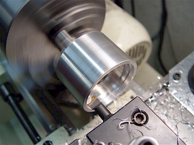
Brazed
Carbide Boring Bar Used on Lathe for Making a Precision Hole (± Ø0.0005”)
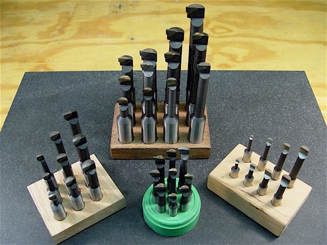
Brazed
Carbide Boring Bar Assortment (for 0.375” and larger bores in ferrous +
non-ferrous materials)
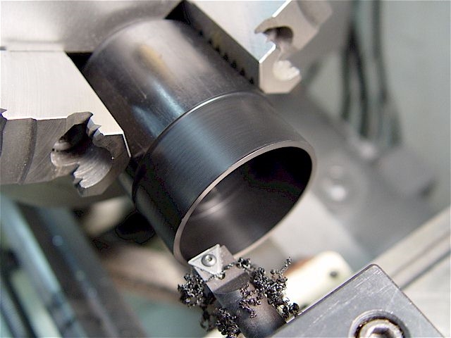
Indexable Carbide Boring Bar Used on Lathe for
Making a Precision Bore (± Ø0.0005”)
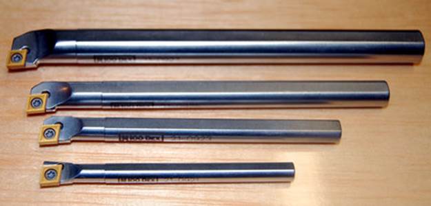
Indexable Carbide Boring Bar Assortment (for
0.375” and larger bores in ferrous + non-ferrous materials)
Process
Tip #1: When possible, drill the part to within a reasonable size prior to boring
because drilling in a much more efficient (i.e. faster) process.
Process
Tip #2: Indexable boring bar inserts have different sized corner radii. Larger corners are stronger and can take
deeper depths of cut. Smaller corners
are more fragile but produce better surface finish. The maximum depth of cut in our labs is twice
the corner radius of the boring bar insert.
Countersinks [RETURN TO T.O.C.]
Countersinks form a cone-shaped
opening at the top of a hole, which acts as a seat for the head of a screw or
rivet. They can also be used for chamferring,
deburring, and creating openings for holding material between centers.
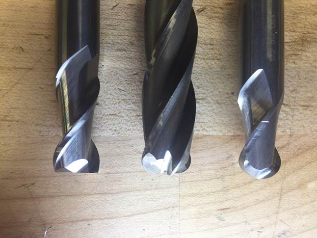
Flutes
Fast Cut
— Have one flute and won't vibrate at high speeds. Also
great for cutting smaller holes.
General Purpose
— Have two, three, or four flutes. Tool life increases with more flutes
because the cutting load is distributed over more edges. However, fewer flutes
provide better chip clearance, which is a consideration when machining stringy
materials like plastic.
Smooth Finish —
Have six flutes. These remove more material per revolution and have a longer
tool life than other countersinks.
Body Diameter and Countersink Angle
The countersink body diameter must be equal to or larger than the head diameter
of the screw, center, or rivet being countersunk. Use a pilot hole that's larger
than 10% of the countersink body diameter.
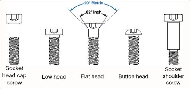
Countersinks of various angles are
available for different purposes:
60° Countersink Angle: For
holding workpieces between the centers on a lathe.
82° Countersink Angle: For flat-
and oval-head inch screws.
90° Countersink Angle: For flat-
and oval-head metric screws. They're also great for chamfering.
100° & 120° Countersink Angles:
Primarily for rivets.
If ordering a countersink, a 90° countersink angle is likely the most versatile.
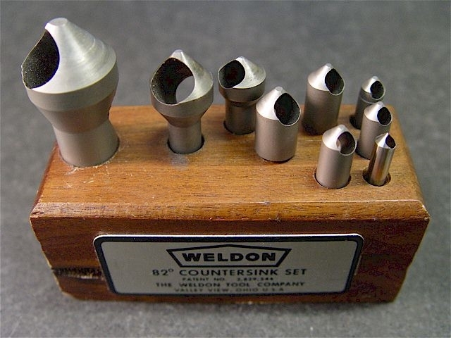
HSS Countsink Set (1/8” – 1” in size)
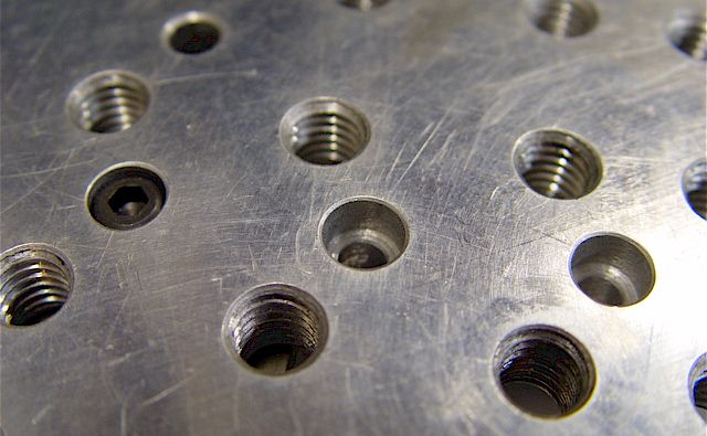
Counterbores [RETURN TO T.O.C.]
Counterboring— Enlarge
the top portion of an existing hole, forming a cylindrical-shaped opening with
a flat bottom that acts as a seat for the head of a screw or wood plug.
Shallow Counterboring—
Bore a shallow spot (1/8" or less) around a hole so that the head of the
screw, bolt, or nut is slightly raised above the surface of the material (also
known as spot facing).
Pilots— A
pilot guides the counterbore as it penetrates the
material, keeping it centered over the drilled screw hole and ensuring a level
seat for the screw head. Counterbores with
built-in pilots have a counterbore and
pilot made from one piece of steel. Changeable-pilot counterbores
have a removeable pilot, allowing you to use various
pilot diameters in a single tool.
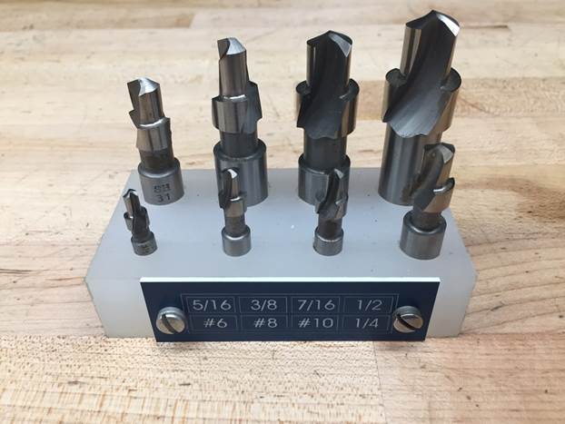
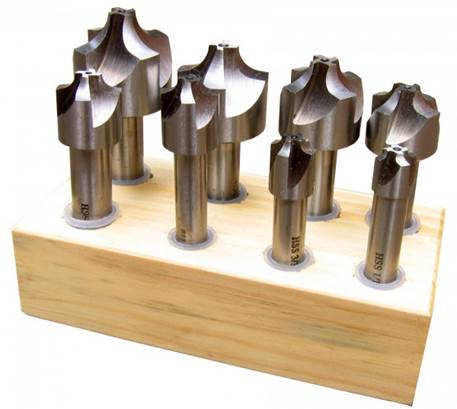
HSS Counterbores (for #6 – #10, ¼”, 5/16”, 3/8”, 7/16”, and ½”
socket head cap screws)
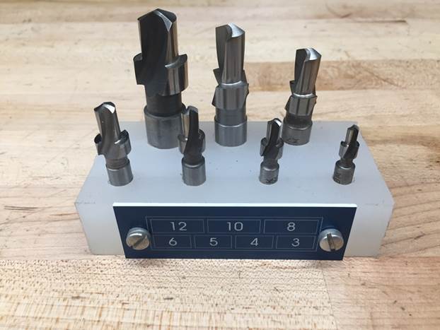
HSS Counterbores (for M3 – M12 socket head cap screws)
An
example of three counter bores for a socket head cap screw (left)
Endmills [RETURN TO T.O.C.]
Basics of … Endmills (Good
Technical Info)
Endmill Nomenclature Figure 1
and Figure
2
Left to
Right: Flat-Bottom, Bull-Nose (aka radius cutter), and Ball-Nose Endmills
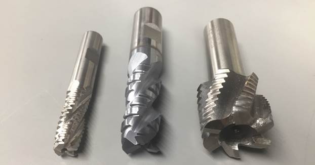
Flat-Bottom
(aka “Square”) HSS Roughing Endmills (sizes ¼” – 1” in 1/8” increments)
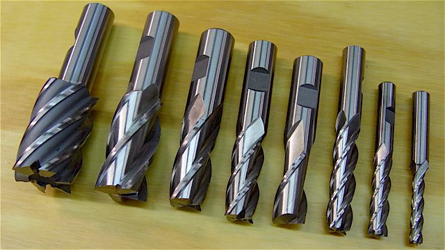
Flat-Bottom
(aka “Square”) HSS Regular Endmills (sizes ¼” – 1” in 1/8” increments)
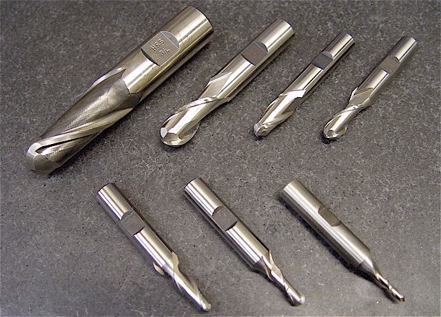
Ball-Nose
HSS Endmills (1/8” – 1” in 1/8” increments)
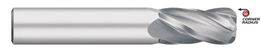
Bull-Nose
HSS Endmills (1/4” to ¾” in 1/8” increments, 0.015”, 0.030”, 0.060” corner
radii)
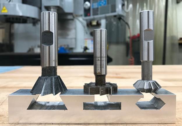
HSS
Milling Cutters (Left to Right: Dovetail cutter, woodruff cutter, 90°
double-angle cutter)
Process
Tip #1: Create
a slot wider than the shank diameter of the cutter and as deep as the desired
feature.
Process
Tip #2: Use
the spindle speed equal to that of a comparable size endmill.
Video illustrating use of
Corner Rounding Endmills
Corner
Rounding HSS Endmills (1/16” – ½” radius in 1/16” increments)
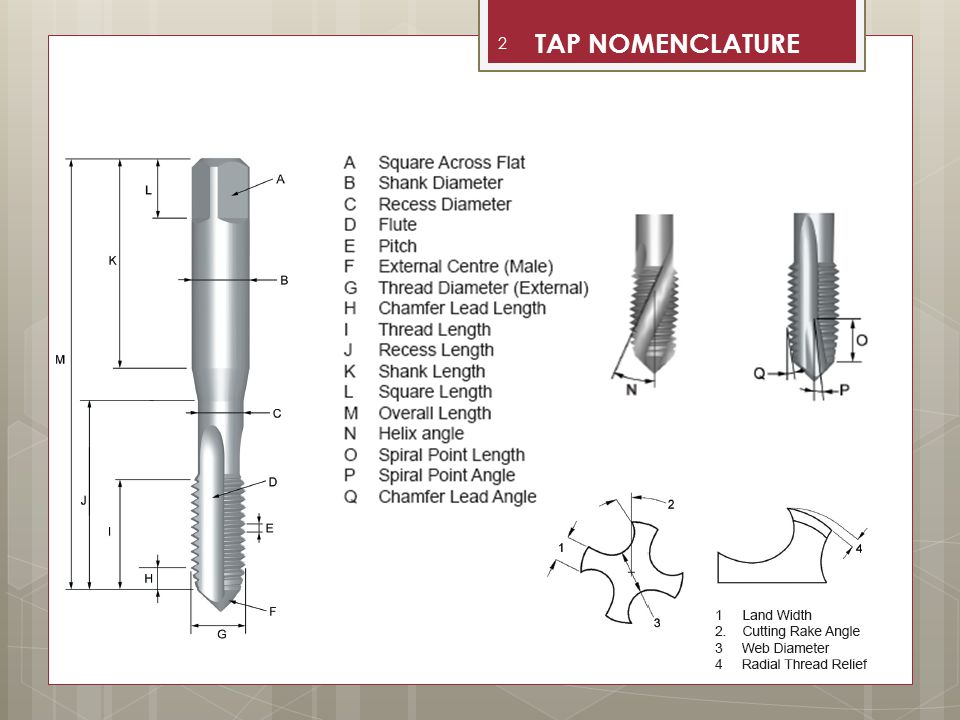
Taps
& Dies & Threads [RETURN TO T.O.C.]
Basics
of … Taps (Good Technical Info)
Types
of Threads (Unified National, Whitworth, Buttress, etc.)
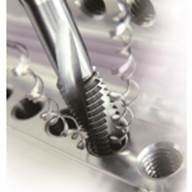
Straight
vs. Spiral Flute Taps and Regular vs. Spiral Tip (aka Gun) Taps (1)
Straight
vs. Spiral Flute Taps and Regular vs. Spiral Tip (aka Gun) Taps (2)

Pulley
Taps and Extension
Taps
STI
(Screw Thread Insert) Taps
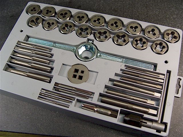
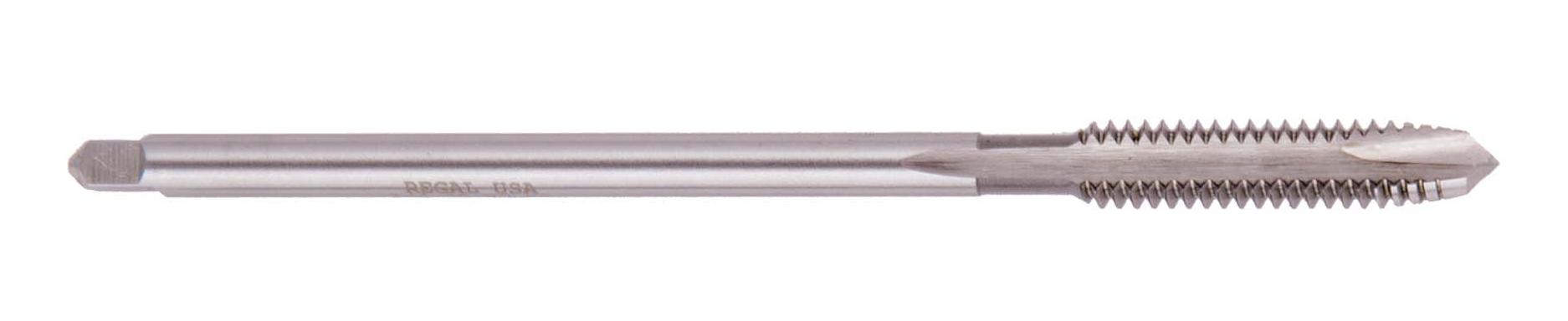
HSS Hand
Taps & Dies (#4 to 1” taps & dies; M4 to M12 taps; M4 to M25 dies)
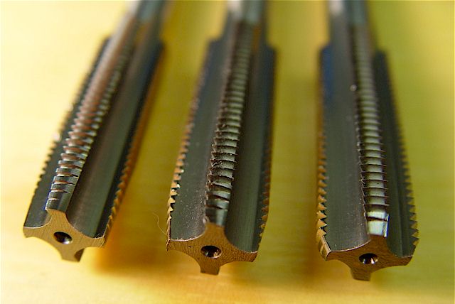
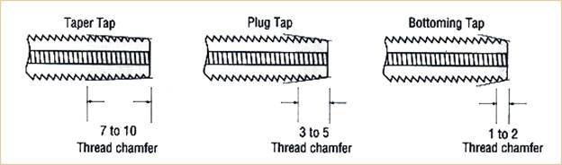
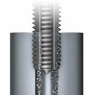
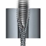
Common
Types of taps: Taper Tap (for starting holes in hard materials), Plug Tap (for
starting holes in easy-to-machine materials), and Bottom Taps (for cutting
threads close to the bottom of blind (i.e. non-thru) holes)
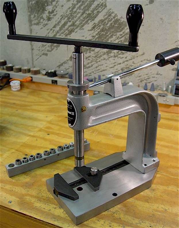
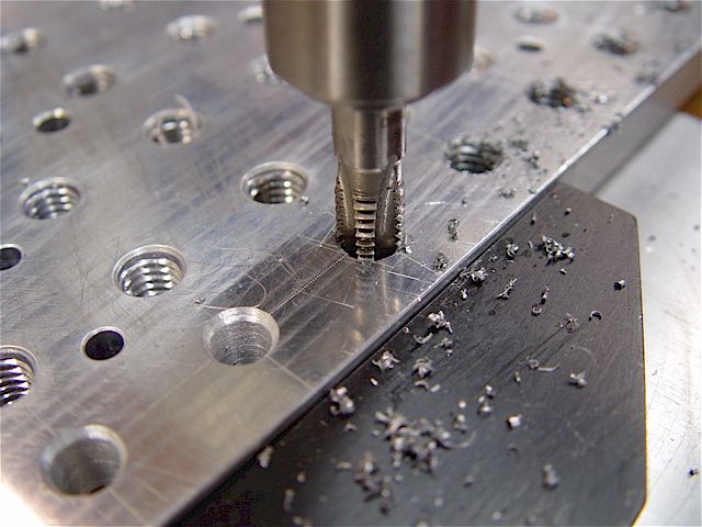
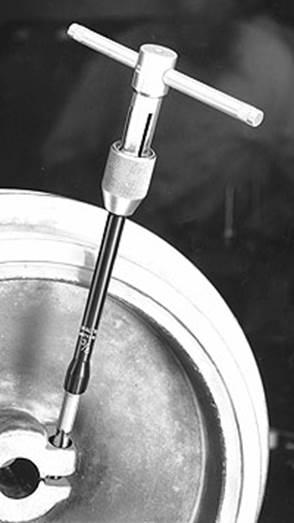
Tapping
Station for Creating Threads Perpendicular to Workpiece Surface
Spring Loaded
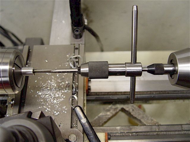
Tap Guide for Creating Threads Co-Axial to Workpiece Centerline
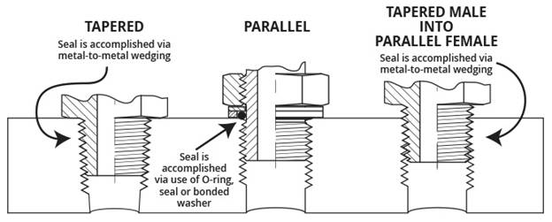
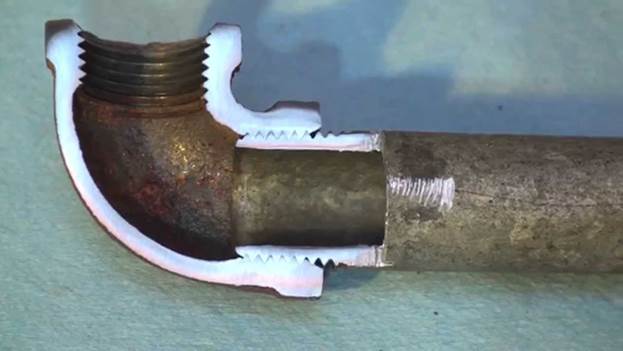
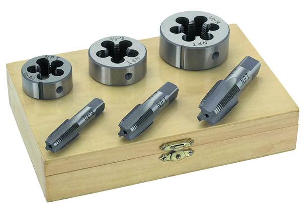
National
Pipe Threads (NPT) Male and Female Taps and Dies (sizes 1/8” to ¾”)
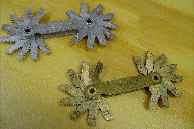
Thread
Gages for Identifying Unknown Imperial or Metric Threads
Instructional
Video on Identifying Thread Pitch and Size
Instructional
Video on Measuring Thread Pitch Diameter Using Thread Wires
Damaged / Stripped
Fastener Removal [RETURN TO T.O.C.]
Braddock Rule #8: Where there are fasteners
and co-workers, there will one day be damaged fasteners! Unfortunately, history proves this statement
correct, so good design engineers should know how to (1) not damage fasteners
when using them and (2) how to repair fasteners damaged by others who didn’t
know better. Read on if you want to be
that fastener guru who impresses your bosses and coworkers with your fastener
removal prowess J.
Before
we talk about some common procedures and tools for removing damaged fasteners,
let’s talk about how they get damaged in the first place; or better yet, how to
NOT damage fasteners when using them.
The
leading cause of fastener damage is ignorance regarding the proper tools for
use installing and removing them. And
with so many crappy tools and false marketing nonsense, it’s not surprising
that most people are confused. So let’s
discuss what we need to properly install and remove fasteners, as well as some
things that may not be common knowledge:
1.
Buy
good quality tools. If you buy the cheap
garbage at (gasp!) Walmart or Harbor Freight, you deserve to mess stuff
up! If you want to not damage everything
you work on, buy a quality set of screwdrivers, L-shaped hex wrenches, L-shaped
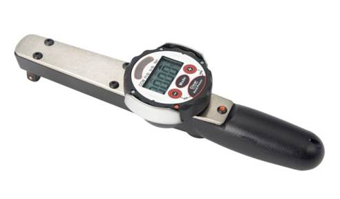
torx wrenches, hex drivers, torx
drivers, impact driver, and torque wrenches.
Here is an
excellent overview of common hand tools.
Yes, this
will run anywhere from $500 - $1,000, so it’s not always feasible on a DIY-er budget, but rarely is the right way also the cheap
way. Starting with screwdrivers, quality
tools possess superior metallurgy, proper fastener engagement, and better
ergonomics. Did you know they make
screwdrivers with hex
bolsters for use applying extra torque with a wrench; with striker
plates and thru shafts for impacting with a hammer to break corroded
fasteners loose; with laser
etched tips to bite into the fastener head and reduce the cam-out effect;
with superior
ergonomics for everyday use; and with high
grip handles for use in greasy or wet environments?
2.
Hex
and torx drivers are included on the previous list of
required tools because it is not safe (for the user or the fastener!) to try
and apply large amounts of torque to fasteners using hand-held wrenches. High torque results in high stresses. High stresses are resisted by higher strength
materials. Higher strength materials are
produced by heat treating (cheaper) or forging (more costly). And heat treating increases a material’s
brittle nature. Could you imagine the
danger in applying a large force through a brittle tool when it breaks? The user would most certainly be
injured. Therefore, most hand-held hex
and torx wrenches are not strong enough to apply the
large loads needed to remove stuck fasteners, which is why we need to invest in
quality metric and standard hex
and torx drivers. In addition, hex and torx
drivers are the only way to install these types of fasteners with a torque
wrench, the use of which is imperative for proper installation!

3.
Most
people have not been taught hex wrenches are consumables and must be reground
(“retipped”) or replaced at frequent intervals due to
the incredibly high contact (Hertzian) stress applied
to the corners of the tips when placed in simultaneous bending and
torsion. The same applies for torx wrenches and drivers, except when these yield or wear,
they must be replaced (unless you want more practice extracting damaged
fasteners!).
Even
screwdrivers need periodic replacement due to wear and yielding (albeit, the
frequency is inversely proportional to the quality).
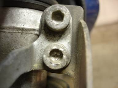
4.
Know
some fastener head types are inherently weaker designs. If you take a lot of things apart (an
activity that teaches invaluable design and assembly skills!), you notice
certain types of fasteners seem more susceptible to damage: button head hex,
low head hex, flat head (countersunk) hex, slotted head screws, etc. In the case of button head, low head, and
flat head hex fasteners, the broached hex is smaller and shallower than a
regular hex head fastener of the same size, which makes the head MUCH more
susceptible to yielding / stripping. In
fact, when properly torqued, low and button head socket cap screws are so much
weaker in this regard, it’s standard practice in
precision machine assembly to never reuse them!
5.
Know
some fastener head types are inherently easier to mix up, with disastrous
results; for example, torx
vs. hex, and torx vs. torx
PLUS!

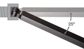
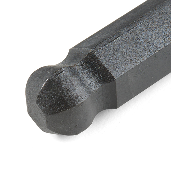
6.
Never,
EVER, use a ball-end hex wrench to tighten or loosen a fastener. The ball end allows convenience off-axis
access to rotate the fastener, but high torque should never be applied using
one, because of the greatly reduced contact area between the major diameter of
the ball and the broached hex in the fastener head.
7.
Understand
cam-out and how to mitigate it. Cam-out
refers to the axial component of the reaction force created when you try to
torque a fastener. Stated another way,
when using a traditional screwdriver with a slotted or phillips head, the more torque you apply, the higher
the axial force becomes which tries to disengage the screwdriver from the
screw. There are many modern
developments in screw drives to reduce this cam-out phenomena, but it will likely continue to
exist in many of the fasteners you deal with in industry. The takeaway here is to apply as much axial force
as possible anytime you are applying a high amount of torque to a phillips or slotted style
fastener. The impact driver discussed
in detail below leverages this understanding of cam-out physics for its
benefit.
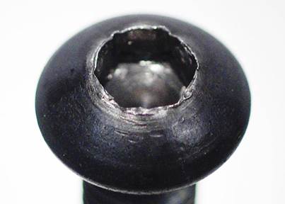
8.
Take
time to prepare hex head screws for removal.
During use it’s common for debris to pack inside the broached hex recess
in the fastener head. If you don’t take
time to remove that debris with a pick, the hex
wrench will not engage as much of the broached hex as possible, greatly
increasing the chance of stripping the head.
9.
When
taking apart fasteners you believe may be corroded or really stuck in place, ALWAYS
take the time to use an impact
driver to shock the fasteners and break them loose. Be careful, however, as these tools are SO
EFFECTIVE they will shear the head of a fastener right off if you set them to
rotate the wrong direction! Click the
previous hyperlink a short application video.

10. Always remember Side’s Rule #1: Your first shot’s
your best shot! Applied to
fasteners, put everything you learned above into action the next time you’re
asked to install or remove stubborn fasteners.
It only takes a little longer to do the things that are going to GREATLY
improve your chance of removing a stuck fasteners, versus spending ten times
longer trying to fix a fastener whose head you stripped.
.jpg)
Now
let’s talk about some common procedures and tools for removing damaged
fasteners:
1.
Often
an impact driver can be used to salvage the head of the fastener and break it
loose at the same time.
2.
Often
applying heat with an oxy-acetylene torch will cause the corroded fastener
joint to expand and contract enough (especially when used in conjunction with a
quality penetrating lubricant like PB
Blaster®), to cause the fastener to loosen.
This obviously only works on components that a little heat won’t damage.
3.
If
dealing with stripped
hex head fasteners, you have some good options.
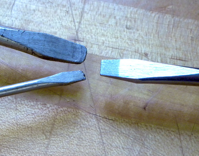
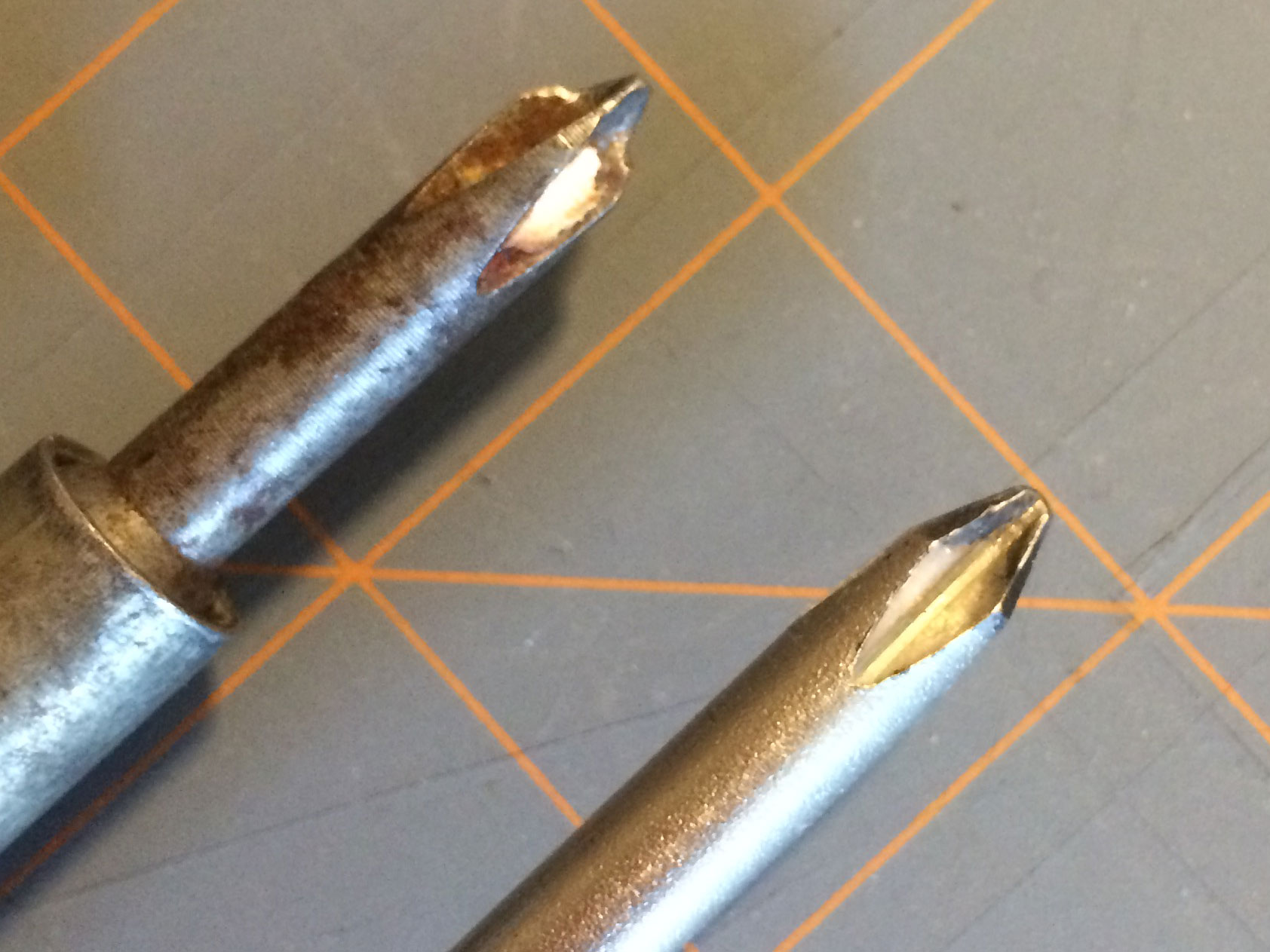
The
cheapest option is to make sure the broached hex is clean and the driver /
wrench is in pristine condition (if not, simple retip
the wrench by grinding a bit off the end).
Next, you can try to file or grind a slight taper on the next larger
size wrench (std. or metric, don’t be afraid to mix in this instance; use the
size differential to your advantage), and hammer the driver into the damaged
hex. If using this option, employ a large
enough hammer to apply sharp impacts to the fastener head, which will help
loosen the threads (like an impact driver).
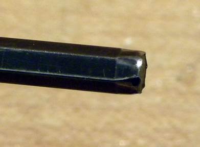
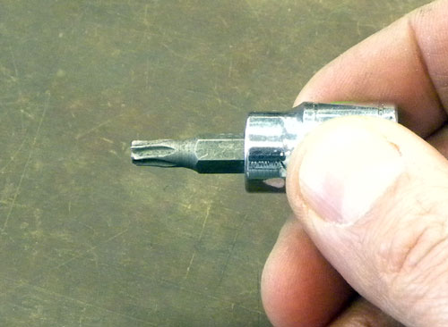
In a pinch, you can also try driving a quality (high strength) torx bit into what remains of the hex head, but this is
usually akin to a Hail Mary late in the game J.
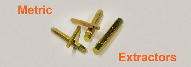
Sock It Out, Inc. makes a commercial version
of these tapered removal tools (for standard and metric hex head fasteners as
well as torx) that make quick work out of removing
stripped hex fasteners (both cap screws and set screws) and torx
fasteners.

4.
If
dealing with fasteners that have sheared, or the head is simply not
salvageable, you have far too many options with which to waste your time, so
let me show you the two that commonly work J :
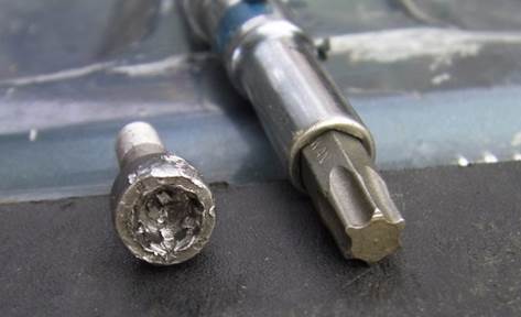
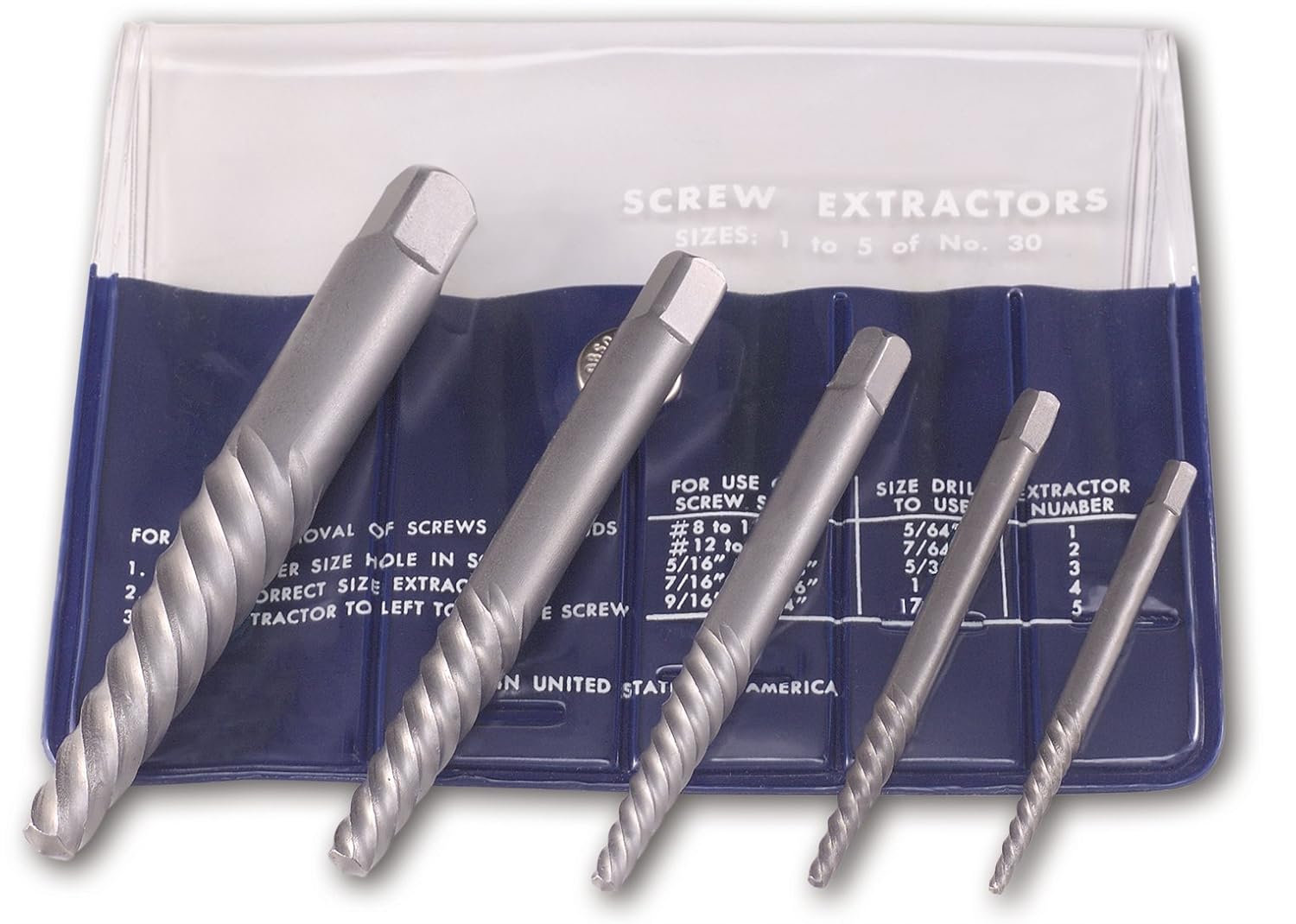
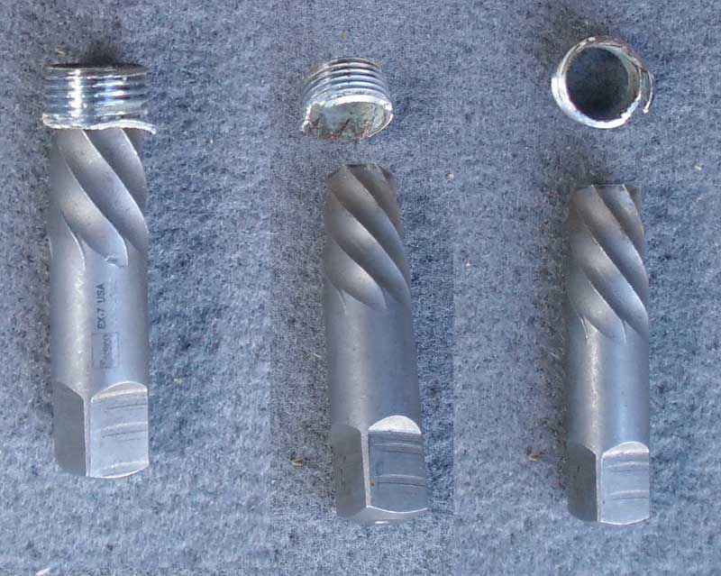
First,
are the ubiquitous spiral flute screw extractors, commonly called Easy-Outs. However, don’t
let the name mislead you, as the only thing easy about using them is snapping
them off inside the broken fastener you’re trying to remove! When using these (or any) extractors, it’s
imperative you drill an appropriately sized pilot hole through the CENTER of the
damaged fastener. The further the hole
is off center, the more likely the extractor is the break.
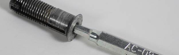
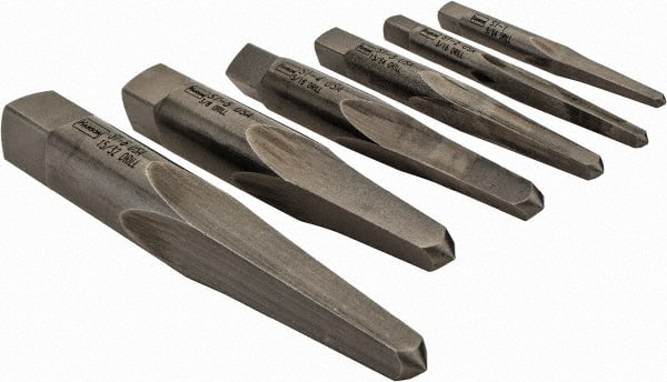
The second style works similar to the first,
however, instead of a reverse spiral, they are simply tapered square punches
which are driven into the pilot hole to lock into the damaged faster shank and
allow reverse torque to be applied. The
spiral flute extractors generally work the best, with the exception of left-hand
threads.
Thread
Repair [RETURN TO T.O.C.]
Corollary to Braddock Rule #8: Where there
are threads and co-workers, there will one day be damaged threads!
Unfortunately, history also proves this statement correct, so good
design engineers should know how to repair damaged threads. Read on if you want to be that fastener guru
who impresses your bosses and coworkers with your thread repairing prowess J.
1. Make sure
whoever you are trying to help with the repair understands you are not
responsible if it doesn’t work out. Far
too often a co-worker will try to fix their mistake before asking for help, and
their attempted fix makes your attempt at repair more challenging! In addition, some co-workers are happy to let
you share the blame for the damaged thread once you lay your hands on it, so
never try to help a co-worker you know is unprincipled.
2. Verify the
correct thread spec. Despite what anyone
tells you, it’s always good for verify the thread size yourself. If there are similar features on the part,
simply check another fastener, or gage another threaded hole.
3. Use a roll /
form tap to try and salvage internal threads by reforming them back to the
original profile. Using a cut tap will
further damage the thread, so don’t try it.
4. If the roll
/ form tap doesn’t fix the problem, and the threads are deep enough in the
part, you can sometimes drill out the damaged threads and use a longer fastener
which can engage more of the deeper, (hopefully!) undamaged threads.
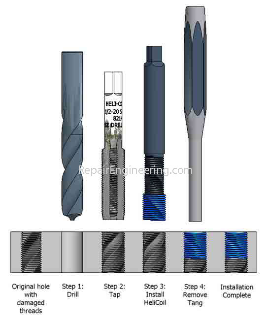
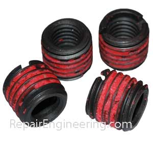
5. If the threads
can’t be salvaged, it’s typically time to consider use of a threaded repair
insert. There are a few quality styles
on the market: EZ-LOKs,
Helicoils, Keenserts,
and Timeserts. Each work well in the proper application and
each have their drawbacks, as shown in these two good product comparisons: one and two.

Note it’s worth your time to research all of these
insert types, because they aren’t just used to fix damaged threads, but also in
many applications where higher surface hardness, lower contact stress, and
higher fatigue resistance are needed when placing thread in non-ferrous
materials. Helicoils
require special STI (Screw Thread Insert) taps, but are used widely in
aerospace applications (perhaps too
widely and for legacy reasons J ?).
EZ-LOKs are available in thin and thick wall versions, which provide
more options.
Cutting
Tool Materials [RETURN TO T.O.C.]
The
primary rule when selecting the proper cutting tool is that the tool material must
be harder/stronger than the workpiece being cut, or the tool will be damaged by
the material. On the
other hand, the stronger the tool material, the more brittle and expensive the
cutting tool. Therefore, much
like selecting workpiece materials, cutting tool materials should be selected
so they are harder/stronger than the workpiece being cut, but not unnecessarily
so.
There
are five categories of common cutting tool materials: high speed steel (HSS),
cast alloys (e.g. Stellite, Tantung, etc.), tungsten
carbides, ceramics, and cermets (ceramic
metals). Conveniently, high speed steel
(HSS) and tungsten carbide (WC) tools comprise over 90% of the modern cutting
tool market, so our discussion will focus on these two materials.
HSS
is the acronym for the most common grade of alloy steel used in the manufacture
of cutting tools. HSS offers good hot
hardness, which refers to its ability to maintain a sharp cutting edge as the
cutting tool elevates in temperature during the machining process. Cobalt can be added to the HSS alloy mix to
provide enhanced hot hardness. HSS also
possesses high toughness, which is the ability of the material to absorb a
significant amount of energy before fracturing.
For reference, the yield strength of HSS is around 45,000 psi. Common cutting tools made from HSS include
drill bits and reamers, endmills, taps and dies, bandsaw and hacksaw blades,
and lathe turning and facing tools.
WC is the abbreviation for tungsten carbide, which
is manufactured by sintering (baking) tungsten carbide powder with binders and
other additives to form solid carbide shapes which are often ground to final
shape. WC has similar properties to
ceramic: it can withstand extremely high temperatures and has a high
compressive strength (450,000 psi), but it is very brittle. WC tools can typically cut workpiece
materials at 2.5 times the speed of HSS, and they typically cost 2 to 5 times
as much.
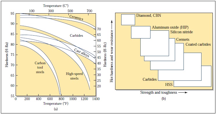
Comparison
of Hardness & Wear Resistance vs. Strength & Toughness of Common
Cutting Tool Materials
Additional
information on Cutting Tool Materials
Cutting
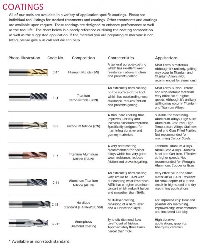
Tool Coatings [RETURN TO T.O.C.]
Several coatings are available for cutting tools for
the purposes of providing high temperature thermal barriers and reducing the
friction coefficients between the cutting tool and workpiece materials. Since heat is the limiting factor for how
fast a particular tool can rotate when cutting a particular material, tool
coatings permit 15-30% higher cutting speeds, while adding about 10% to the
cost of the tool. Common coatings
include black oxide, titanium nitride (TiN), aluminum
titanium nitride (AlTiN), titanium carbonitride (TiCN), and
zirconium nitride (ZrN).
Coatings are generally not useful when tools are
used on manual machines because of the lower spindle speeds and the fact that
most tools will be damaged in use by accidentally feeding them too aggressively
as opposed to developing dull edges due to extensive use.
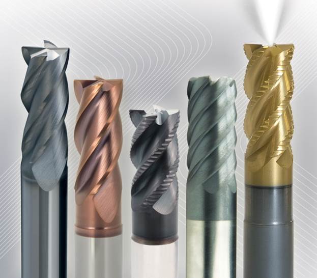
Common
Cutting Tool Coatings Applied to Finishing and Roughing Endmills
Harvey
Tool’s Excellent Tool Coatings Chart
Metrology [RETURN TO T.O.C.]
10:1 Rule – The resolution of the measuring
instrument should be ten times greater than the feature to be measured. For
example, if the length of a part is specified with a 0.005” tolerance, it must
be measured with an instrument with a resolution 0.0005″.
An
excellent quick guide to understanding errors in hand-held measuring
instruments can be found here
A
comprehensive guide to precision measuring instruments can be found here
Standards
Standards are
objects that have been certified by NIST to
meet certain dimensional accuracy targets. They are used as a reference for the
calibration of measuring equipment such as calipers, micrometers, and dial
indicators. There are several grades available: reference (AAA), calibration
(AA), inspection (A), and workshop (B). Since metals expand at a rate of
approximately 0.000010″/°F, all certification measurements occur at a
standardized 68°F (20°C).
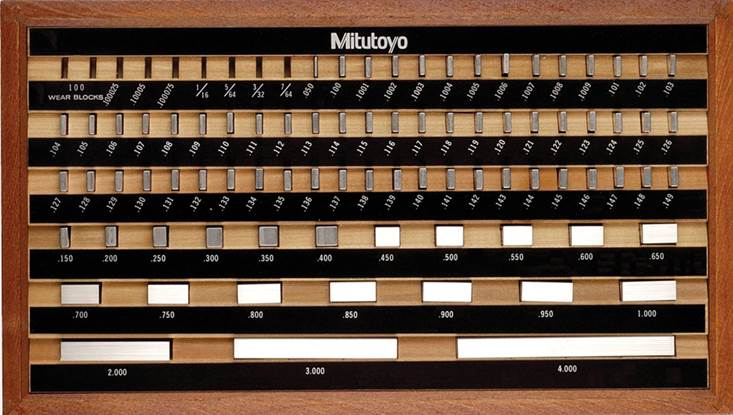
Gauge Block Set (accurate to ±0.000050″;
blocks can be joined with very little dimensional uncertainty)
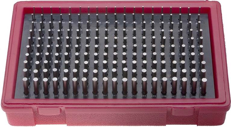
Gauge Pin
Set (accurate to ±0.000050″; may also be used to determine the size of a
hole to ±0.001″)
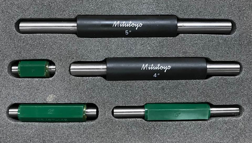
Micrometer
Standards (for setting the zero point of outside micrometers; 1″ standard
accurate to ±0.000050″; 5″ standard accurate to ±0.00015″)
Outside Measurements
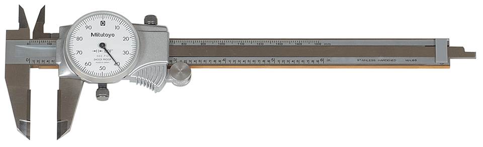
6″
Dial Calipers can measure outside, inside, depth, and shoulder measurements
·
Accurate
to ±0.001″ / ″ of travel; this error compounds linearly (i.e. a 6″
measurement taken with it is only accurate to ±0.001″)
·
Prone
to Abbe error, which says that a source of error is introduced anytime the
reference line of a measuring system doesn’t lie along the same line as the
dimension being measured
·
Prone
to parallax error, where the observed measurement changes depending on the
viewing angle
·
The
ID measuring jaws are offset from one another, which means the jaws will never
“find” the maximum diameter of the workpiece
·
No
way to limit applied pressure, resulting in a lack of repeatability and
reproducibility
·
Can
improve accuracy by calibrating with a standard that is close to the size being
measured
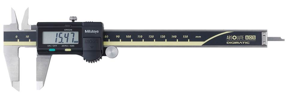
6”
Digital Calipers
·
accurate
to ±0.001″ over the entire 6″ range of travel
·
still
prone to each of the errors listed above, excluding parallax error
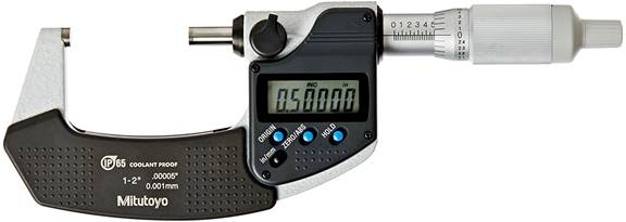
OD
Micrometers
·
accurate
to ±0.000050″
·
according
to 10:1 rule, can measure features to ±0.0005″
·
spindle
has a torque limiting ratchet or clutch to improve repeatability and
reproducibility
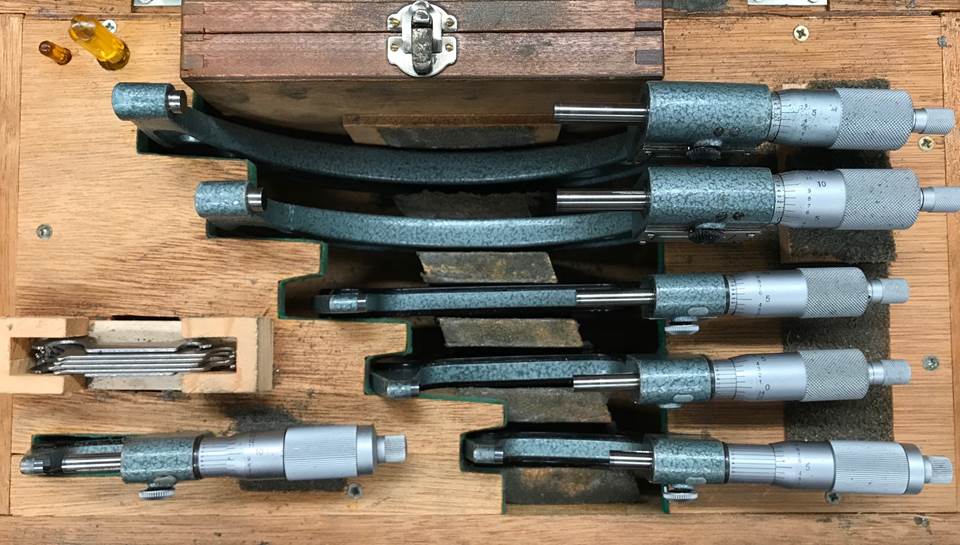
Set of
1-6″ OD Micrometers
·
each
micrometer has a range of 1 inch
·
set
includes 0-1″, 1-2″, 2-3″, 3-4″, 4-5″, 5-6″
micrometers
·
limiting
the travel of the spindle results in a more accurate measurement
·
any
quality micrometer will come with a standard that can
be used to zero the micrometer
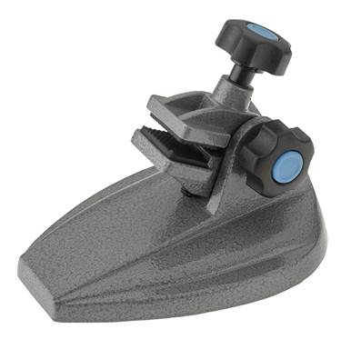
Micrometer
Stand (used to hold micrometers to minimize heat input from the user and hold
the micrometer steady when measuring)
Inside Measurements
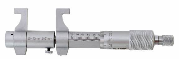
ID
Micrometers (accurate to ±0.0003″)
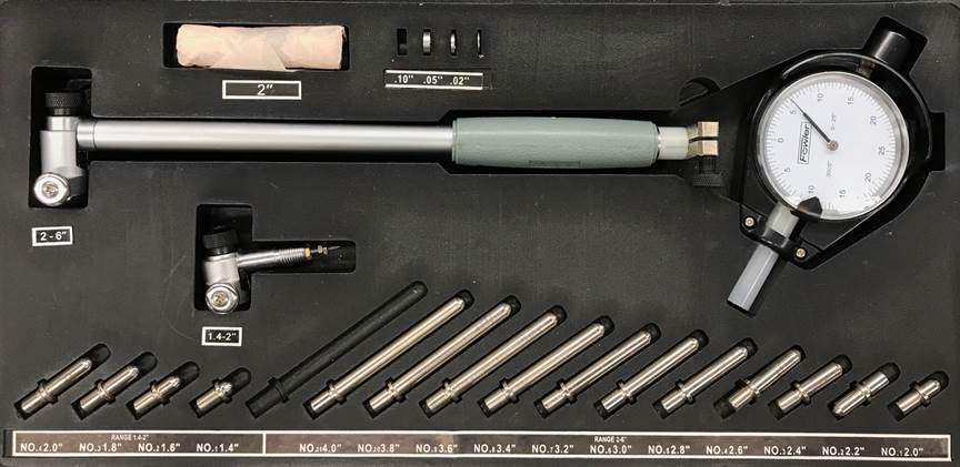
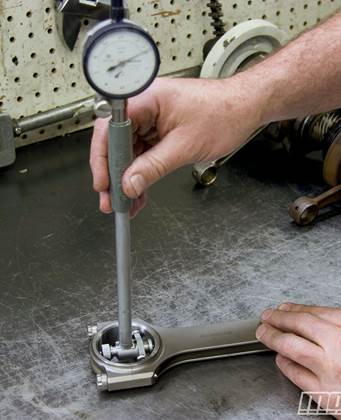
Dial Bore
Gauge (the dial indicator is zeroed at the desired measurement using a micrometer, and the relative displacement is used to
determine bore size)
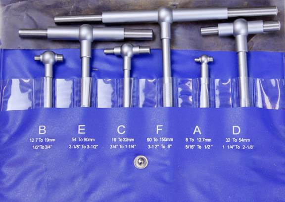
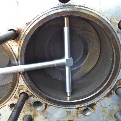
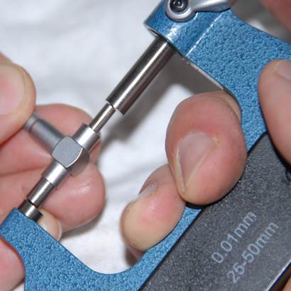
Telescoping
Bore Gauge (the gauge has two spring loaded cylinders that are pushed into
contact with the interior of the bore and a locking mechanism to retain the
bore size once removed. A micrometer is then used to measure the bore gauge.)
Relative Measurements
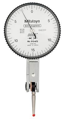
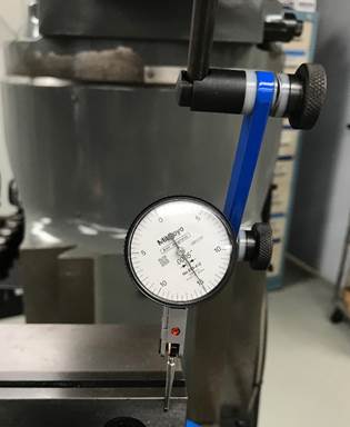
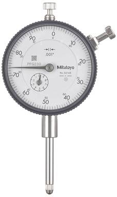
Dial
Indicator (accurate to ±0.001 - 0.0002″ depending on indicator; shown
above measuring the straightness of a vise jaw)
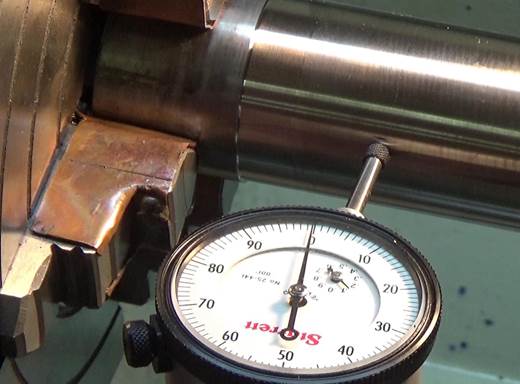
Drop
Indicator (accurate to ±0.001 - 0.0001″ depending on indicator; shown
above measuring the concentricity of a part in a lathe chuck)
Other
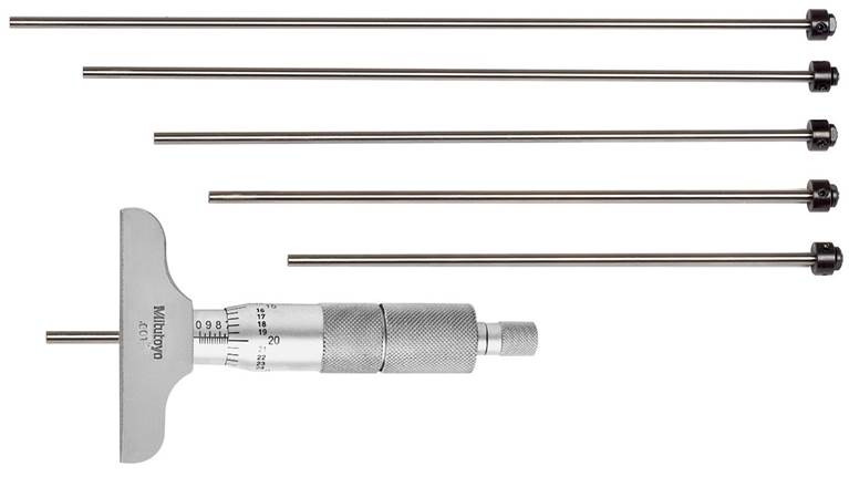
Depth
Micrometer (accurate to ±0.0001″ for the micrometer head, varies per
measuring rod length)
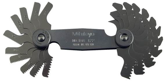
Thread
Pitch Gauge (used to determine thread pitch)
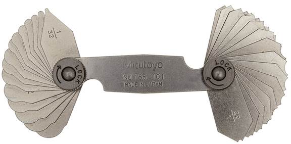
Radius
Gauge (used to determine the size of internal/external radii)
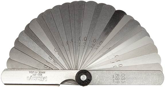
Feeler
Gauge (used to determine thickness, usually of a gap)
Electronic Measurement
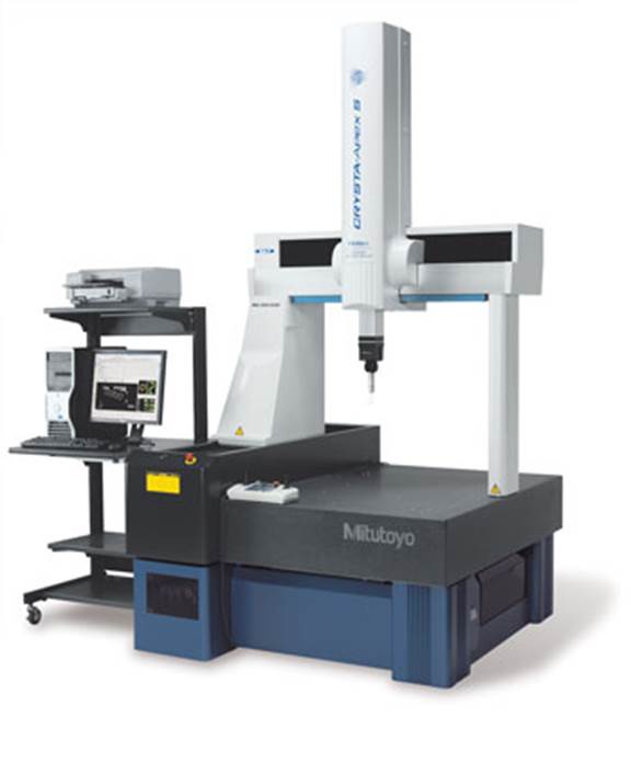
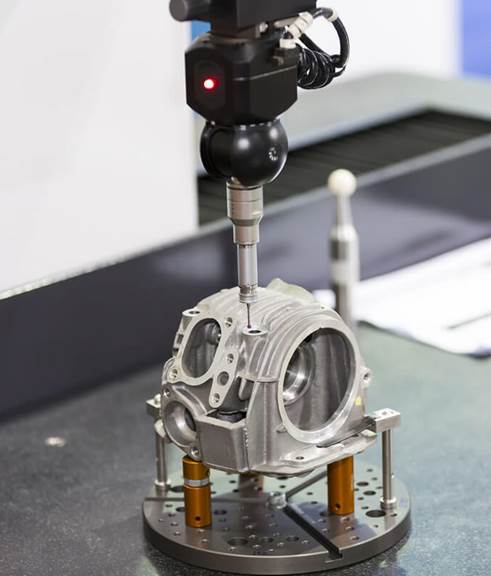
Coordinate
Measuring Machine (accuracy up to ±0.000015″; measurements are made with
a probe mounted on a multi-axis head)
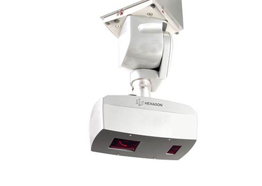
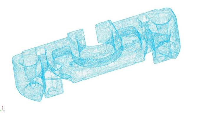
Laser
Scanning (creates a point cloud of an object, high-end sensors can have a point
spacing of as small as 0.001″)
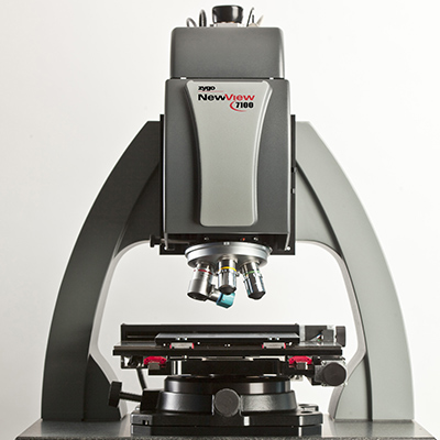
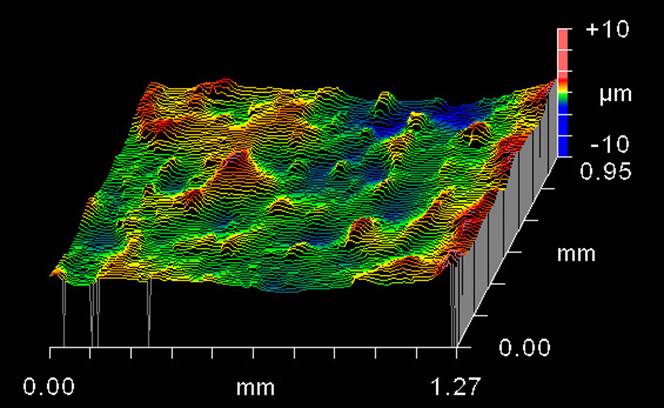
White
Light Interferometry (non-contact method for measuring surface profiles to
±0.000005″)
Photo copyright notice:
many of the photos and content on this page are taken from Micro-Machine Shop, which does an
excellent job organizing and presenting it.